

Fibre optic infrastructure on an airport site
A 12-core fibre backbone for air traffic and operations systems
 08
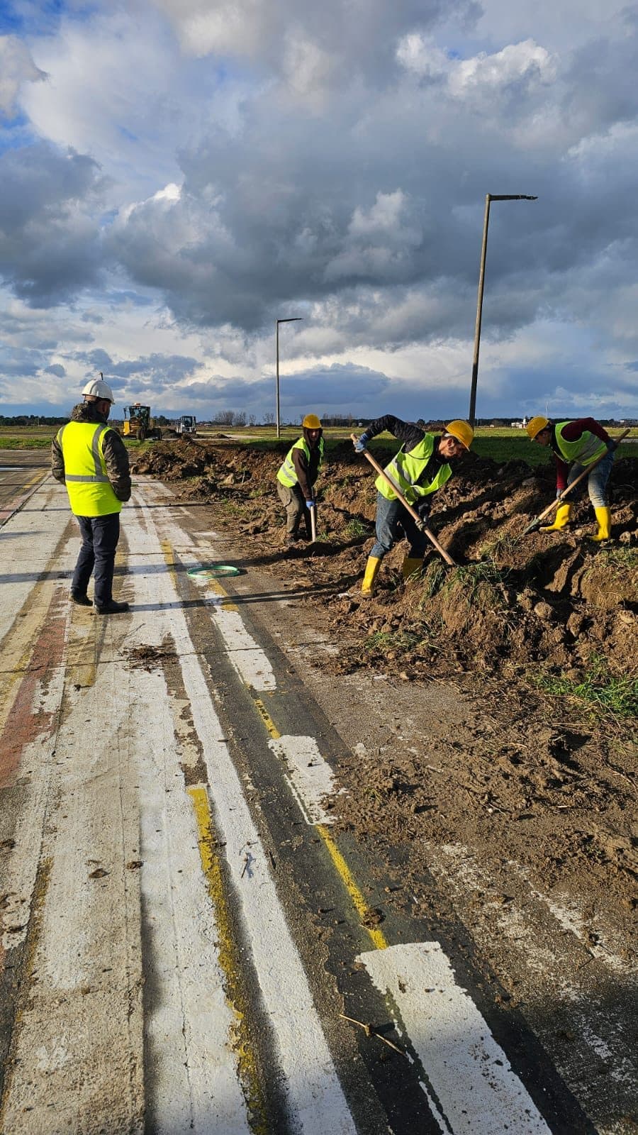
08A 12-core fibre optic backbone built for air traffic control and operations systems at an airport in Samsun, completed on night shifts without interrupting operations.
- Customer
- Bir havalimanı işletmesi
- Sector
- Communications infrastructure
- Location
- Samsun, Türkiye
- Field of work
- Power and infrastructure
- Year completed
- 2024
The need
What had to be solved on site?
An airport is one of the hardest sites for infrastructure work. Air traffic control and operations systems cannot be interrupted, yet the fibre route had to pass through areas carrying aircraft and vehicle traffic.
The second difficulty is that the work will need maintenance later. If every further pull or fault intervention on a buried fibre route meant digging again, airport operations would be affected each time.
How we solved it
A 12-core fibre optic backbone feeding the air traffic control and operations systems was installed at an airport in Samsun. The scope comprised trenching, HDPE ducting, single-mode fibre pulling, splicing and OTDR measurements.
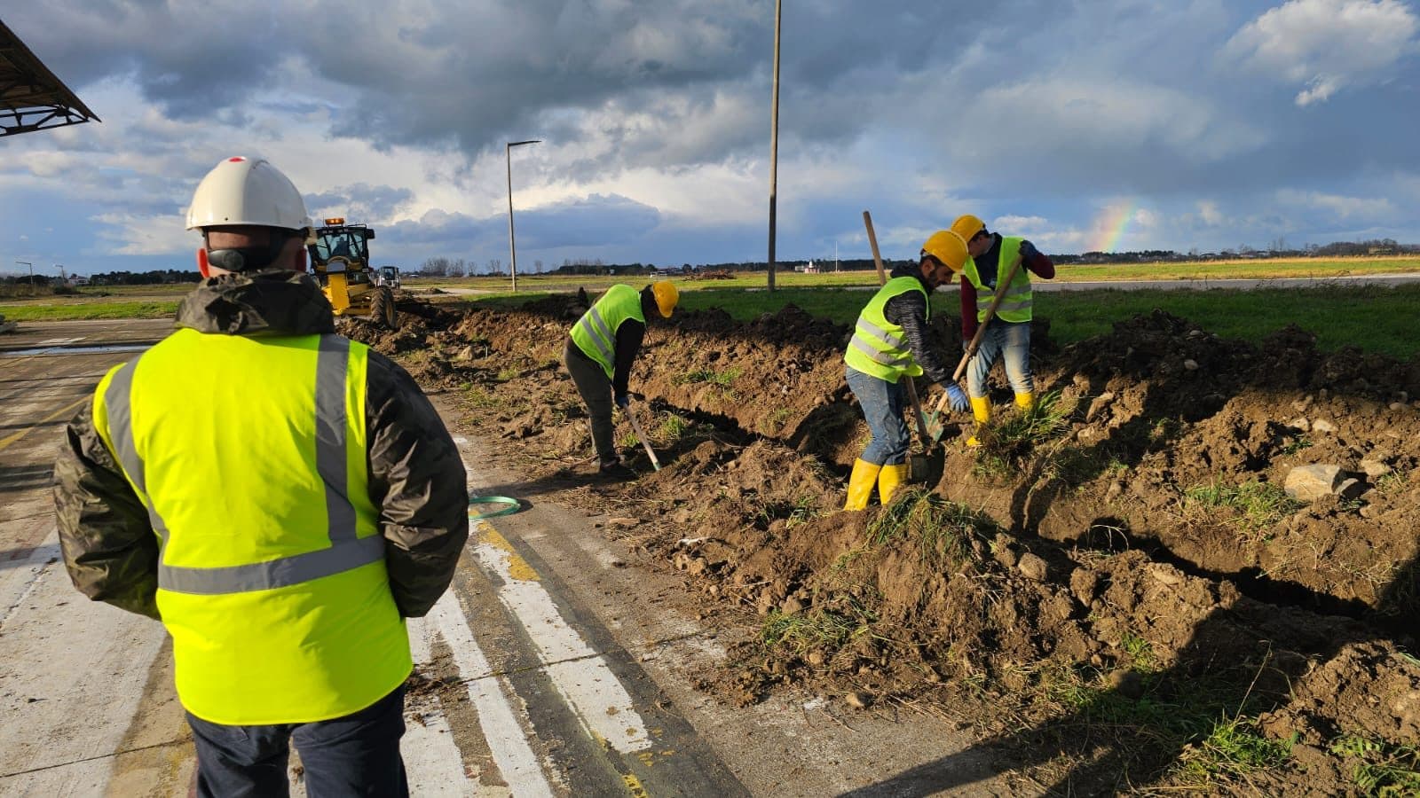
Airport operations never stopped: the work was scheduled onto night shifts, the route was broken by a manhole every 20 metres, and tray work completed the runs inside the buildings. The manhole spacing was chosen so that future pulls and maintenance are possible without excavation.
Before handover, loss was measured with OTDR on every line; the measurements showed additional loss of 0.3 dB or below on all runs. The project was delivered together with as-built documentation.
The work was scheduled entirely onto night shifts. Each excavated section was closed and made safe at the end of every shift, so no open trench was left on site when operations resumed in the morning. This arrangement lengthened the job but meant operations did not stop for a single day.
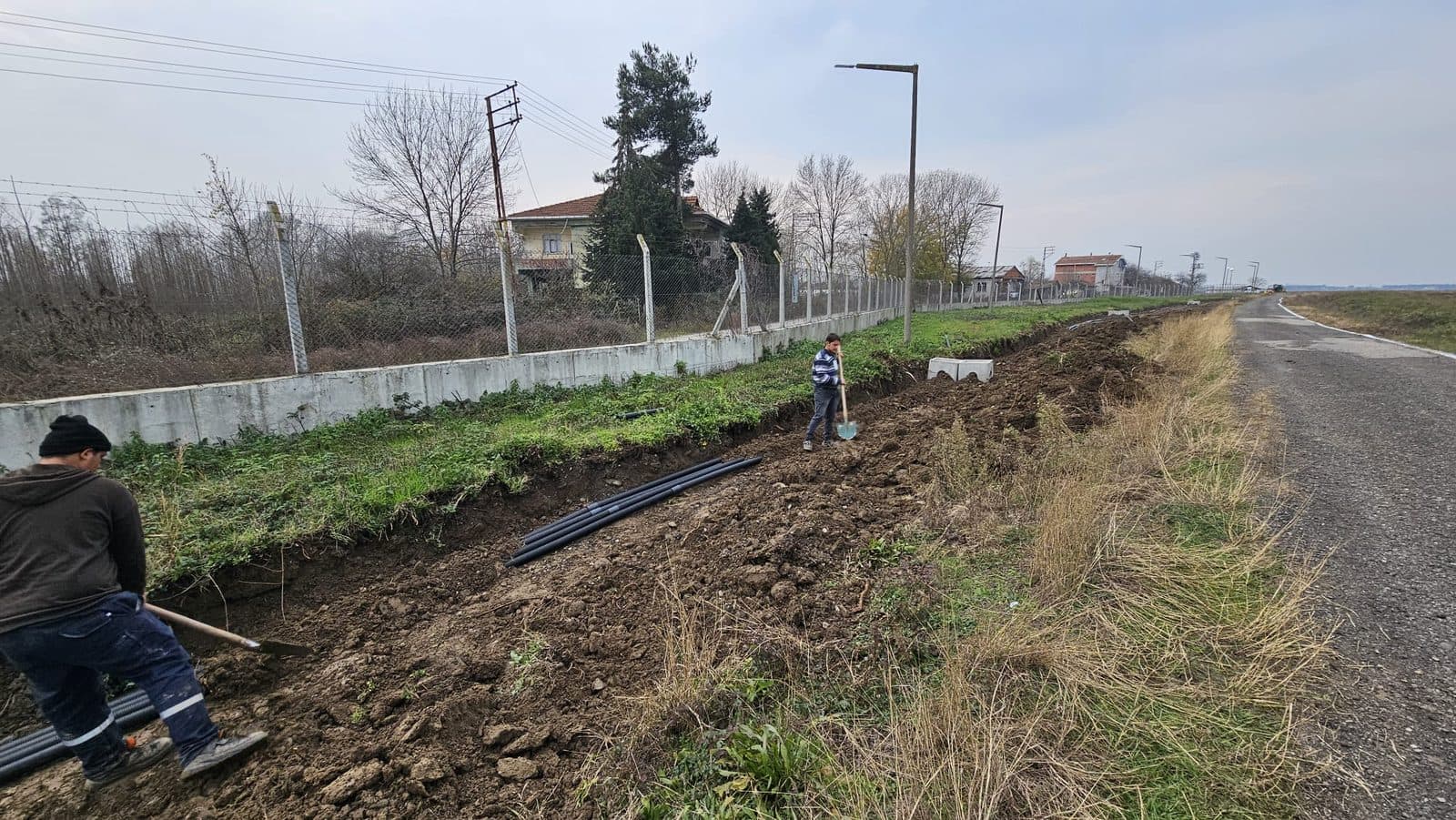
The manhole spacing was set at 20 metres. That distance is not arbitrary: it is a spacing at which fibre can be pulled comfortably between two manholes without exceeding the permitted pulling tension, and at which future pulls need no excavation. On sites like an airport where digging is expensive, widening that spacing means saving on the first investment and making every later intervention costlier.
Cable tray work was used for the runs inside buildings. A tray carries the fibre freely and tidily, removing the risk of crushing and sharp turns. The tray route was sized to leave space for lines added later.
Before commissioning, OTDR measurement was carried out on every run. OTDR shows how the light attenuates along the fibre, revealing the loss at splice points and any loss caused by bending. Additional loss stayed at or below 0.3 dB on all runs, and the measurement outputs were added to the as-built file.
The order we worked in
- 01
Night-shift planning
Excavation and pulling were moved outside operating hours, and the site was made safe at the end of every shift.
- 02
Setting the manhole spacing
The 20-metre spacing was chosen with pulling tension and future maintenance without excavation in mind.
- 03
Splicing and termination
Splices were made and protected inside the manholes, and terminations were completed on the in-building tray route.
- 04
OTDR measurement and documentation
Every run was measured with OTDR and the results were handed over as a file together with the as-built drawings.
- Fibre capacity
- 12-core single-mode
- Manhole spacing
- 20 metres
- Measured additional loss
- ≤ 0.3 dB
- Operational downtime
- None
What this changed on the floor
- 01
High capacity
Strong, expandable data transmission with 12-core fibre.
- 02
Maintainable route
A 20-metre manhole spacing makes further pulls and maintenance possible without excavation.
- 03
OTDR-verified runs
Measured additional loss stayed at or below 0.3 dB on every run.
- 04
No operational downtime
Scheduled onto night shifts, the work never interrupted airport operations.
Project images
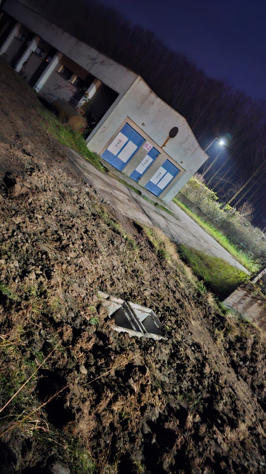
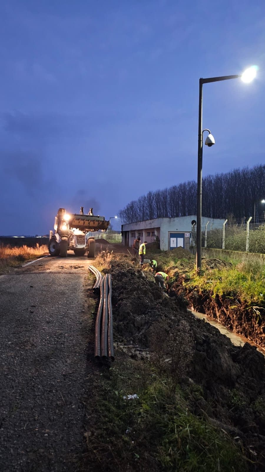
Evening site work along the route where manhole and ducting work continues
Frequently asked about this application
What is OTDR measurement for?
OTDR measures the light reflected back along the fibre and shows where loss occurs on the run. Loss at splice points, loss caused by over-bending and any break point appear in this measurement to within metres. Doing it before commissioning eliminates problems that would otherwise surface later.
Is 0.3 dB additional loss a good value?
On single-mode fibre, a well-made fusion splice typically loses around 0.1 dB. Where a run has several splices, the losses add up. Staying at or below 0.3 dB on every run shows that both splice quality and bend management along the route were done correctly.
Why is the manhole spacing 20 metres?
The spacing balances two things: being able to pull the cable without exceeding its permitted tension, and not needing excavation for a later pull or fault intervention. Widening the spacing lowers the first investment but makes every subsequent intervention costlier. On sites like an airport, where digging affects operations, closer manholes are more economical in the long run.
Does working without stopping operations raise the cost?
On the labour side, yes: night shifts and closing the site at the end of each shift lengthen the job. But that stays small next to the cost of stopping operations. On sites like an airport, the cost of downtime far exceeds the cost of the work.
Do you have a similar need on your line?
Describe the defect you need to catch or send a photo of your production line, and we will assess feasibility and the hardware needed together.
Have a project or a material list?
Send us your list; we return stock status, lead time and wholesale pricing the same day.